Kandi Kruiser • 48V lead-acid conversion
Give your Kruiser a simpler battery routine. This guide shows how a Fleet Lithium conversion comes together, using real installation photos and clear instructions for the details that matter: tray clearance, charging controls and your dash display.
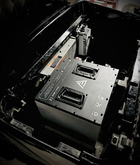
Can a Kandi Kruiser run on lithium? Yes—compatible 48V lead-acid Kruiser 4P and 6P configurations can use a matched Fleet 51.2V lithium system. Replace the complete lead-acid bank with the correct battery, mounting kit, lithium charger and charge-level display. The installation shown uses one 105Ah battery.
Manual FL-IM-KAN-48 • Revision 1.0 • 12 pages • Real installation photos and a fillable installation record.
Why move your Kruiser to Fleet Lithium?
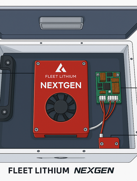
A single lithium pack simplifies the battery bay and eliminates the series links between six separate traction batteries. You also gain a battery-specific charge reading through the Fleet gauge and supported app, rather than relying on dash bars calibrated for lead-acid. Choose the capacity around your passenger load, terrain and driving routine.
The Fleet Kandi bundle brings the battery, vehicle mounting hardware, matched lithium charger, power connections and SOC gauge together. Confirm the exact contents of your selected order. The Kandi-specific 5-inch replacement screen is an optional product, not an assumed inclusion in every kit.
Confirm your vehicle before ordering
Photograph the model/serial label, complete battery bank, controller label, original charger and its connectors. Documented lead-acid Kruiser 4P/6P configurations use six 8V 150Ah AGM batteries for a 48V bank. Check your actual vehicle: the badge and model year alone do not identify its electrical layout.
This manual follows a single-pack 105Ah installation. Factory-lithium vehicles, a two-pack 210Ah conversion, and other Kandi models such as Pro, Mini, Cowboy or UTV require their own fitment and wiring confirmation. A product listing's broader model range does not make every step in this photo sequence universal.
Keep any separate 12V supply and the vehicle's DC-DC converter identified. A converter powered from the new traction pack must accept its 58.4V maximum. Lights, a horn and other 12V accessories must never connect directly across the traction battery.
Choose capacity around your driving
| Capacity | Nominal energy | Planning guidance |
|---|---|---|
| 65Ah | 3.33 kWh | Only for an approved stock motor/controller and load. |
| 105Ah | 5.38 kWh | The single-pack installation photographed in this manual. |
| 168Ah | 8.60 kWh | More stored energy; confirm case, bracket and seat clearance. |
| 210Ah | 10.75 kWh | Two matched 105Ah packs; separate mounting and parallel-wiring instructions required. |
More amp-hours provide more stored energy, not a guaranteed mileage figure or a higher vehicle payload rating. Passenger weight, speed, hills, tire size, temperature and accessory loads all affect range. Send Fleet your vehicle photos if the controller, tray or connectors differ from the guide.
The installation, in the right order
1. Isolate power and remove the old bank
Park level, set the brake, select Neutral, remove the key, chock the wheels and unplug AC. Follow Kandi's power-isolation procedure, including any separate 12V supply. Label the complete bank's main positive and negative cables, charger leads and accessory feeds. Disconnect bank negative first, then positive; insulate the ends. Remove links, restraints and batteries with suitable lifting help.
Clean and dry the bay. Repair corrosion, damaged cables or loose tray mounts before fitting the kit. The photo sequence begins after the old batteries have been removed.
2. Bend the interfering tray tabs and fit the base
With the Fleet battery outside the bay, trial-position its base. Move wiring clear, grip each interfering original raised tray tab with adjustable pliers and bend it gradually down out of the battery footprint. Do not bend the tray rails or Fleet bracket. Check for cracks, smooth burrs and protect exposed metal against corrosion.

Align the base with the existing mounting points, start all supplied fasteners and tighten to the hardware instructions. No frame drilling is required for the photographed arrangement. The base must sit securely without trapping a cable.
3. Secure the pack and connect the identified main cables
Keep the battery OFF. Lower it upright onto the base, fit its restraint and verify it cannot slide, lift or rock. Close the seat slowly to check the hinges, underside and cable clearance. Leave the battery switch, ports and pressure-relief device accessible.
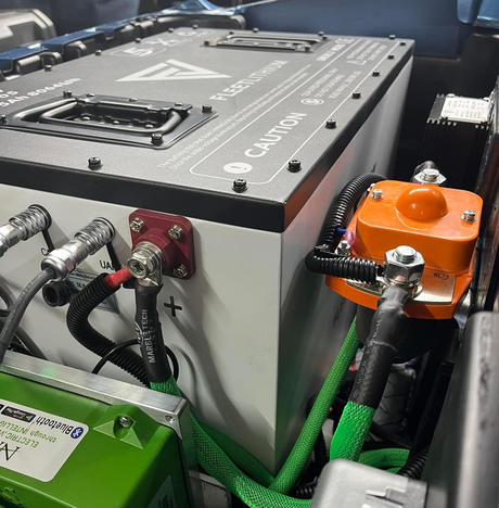
Connect the labeled vehicle positive to B+, then vehicle negative to B−. Retain the main fuse/disconnect. Use the supplied terminal hardware and the torque specified for your battery; refit both insulating covers. Keep motor/controller wiring in place. The chassis is not the battery-negative connection.

4. Replace the charger and complete the inlet
With all battery supplies isolated and AC unplugged, label the old charger's AC input, DC output and small control plug separately. Support and remove the old charger. Save its small two-wire charger-side plug for the procedure below; leave the matching vehicle harness intact.
Secure the supplied Fleet charger with its cooling surfaces clear. The photographed kit uses CH5618, rated 58.4V/18A. Route its positive and negative DC outputs through the supplied charge harness to the correctly identified battery terminals. Fit the specified grounded inlet and AC connection, including AC0219 where supplied, with its seal, cover and cable strain relief. Connect a supplied remote status lamp only to the charger's designated indicator lead. The lamp shows charger status; the Fleet gauge shows battery charge.
Build the original two-wire interlock bypass
This procedure applies only to the original small two-wire charger-control circuit shown in the manual. Identify the connector and circuit—not just wire colors.

- Save the plug. With AC unplugged, battery supplies isolated and the old charger removed, cut its two small control wires near the disconnected charger, keeping sufficient tails on the plug. Do not cut or join AC input or main DC output wires.
- Make a sealed loop. Strip to the splice manufacturer's specified length. Join the two tails using an insulated, adhesive-lined heat-shrink butt splice sized for the wire gauge and circuit voltage. Crimp each end with the correct tool, gently pull-test, then shrink the seal with controlled heat away from the battery and connector.
- Test before reconnecting. Check continuity between the two populated plug contacts. The reading should be close to the meter-lead resistance and remain steady when the tails are moved gently. Leave no exposed copper. The manual's photos document the original twist-and-tape sequence; the finished connection must use the sealed crimp described here.
- Reconnect and secure. Seat the plug in the original vehicle socket and latch it. Secure it to the fixed harness away from steering, suspension and sharp edges. Label the inlet: UNPLUG CHARGE CORD BEFORE DRIVING.
A different connector or circuit needs its own instructions. Do not bridge the contactor or other unidentified wiring to make the vehicle drive.
Choose your charge display
Round gauge: flush dash or included mount
For a flush installation, verify the supplied gauge needs a 2-inch (50.8 mm) cutout, inspect behind the dash, move wiring clear and cut squarely with a 2-inch hole saw. Deburr, remove chips and fit the gauge and retainer without distorting the panel. Alternatively, use the included 2-inch mount in a visible position clear of controls. Check behind every fastener location.
With the pack OFF, route the matched cable away from pedals, steering and seat hinges. Connect to the labeled display port or harness specified for your battery revision. Do not put pack voltage on a data connector or split a cable to feed two displays unless the supplied harness supports it.
Optional Kandi-specific 5-inch replacement screen
Use FL-LCD-KANDI, programmed for Kandi, when applicable to your vehicle and order. The ICON version is different. Page 10 of the manual shows the actual screen and rear connector housings.
- Photograph the original display, odometer, rear plugs and mounting hardware. Record the mileage; do not assume it transfers. Unplug AC and isolate traction and any separate 12V power.
- Open the rear dash access, support the cluster, release its plug latches and pull on connector housings. Remove its retaining hardware and screen; retain the seal for comparison.
- Seat the replacement in the original opening with its specified seal and hardware. Reconnect matching keyed vehicle plugs or the supplied adapter without forcing, re-pinning or splicing them.
- If provided, route the separate Fleet battery communication lead exactly as its identified harness instructions specify. Do not substitute a round-gauge cable or guess a CAN pinout.
- At startup, check voltage/SOC, fitted indicators and faults. During the low-speed test, check speed. Compare SOC with the Fleet app. Modified controllers, tire sizes or gearing can require configuration.
First charge and your first drive
With key OFF and AC unplugged, check restraint, polarity, specified torque, covers, inlet, charger-control connection and gauge. Remove tools and close the panels. Switch the Fleet battery ON using its instructions, then turn the key ON. Check charge level, faults and fitted accessories.
Turn the key OFF, set the brake and complete the first full charge from a suitable grounded AC supply. Do not override temperature or other battery protections. Unplug and stow the cord, then test forward, reverse, steering and brakes at walking speed in a clear level area. Stop for unusual heat, smell, noise or faults. Switch off and reinspect before normal use.
For storage longer than a month, use approximately 50–60% charge, unplug AC and switch the pack OFF. Address accessory drains and check charge about every 90 days. Maintain any separate 12V battery according to its own instructions.
Kandi lithium conversion questions
Can I convert my 48V Kandi Kruiser to lithium?
A compatible 48V lead-acid Kruiser 4P or 6P can use a matched Fleet 51.2V lithium conversion kit. Verify the actual battery bank, controller, charger connectors, tray and selected capacity before ordering. This photo guide follows one 105Ah pack; it does not establish fitment for every model year, factory-lithium Kandi or other Kandi vehicle.
Do I need to bend the Kandi battery tray tabs?
On the photographed tray, raised original tabs interfere with the new battery footprint. With the battery outside the bay, bend only the interfering tabs down using pliers. Do not bend the tray rails or Fleet bracket. Check for cracks, smooth burrs, protect exposed metal and verify clearance before lowering the battery.
Can I keep the original lead-acid charger?
Replace it with the lithium charger supplied for your Fleet kit. The photographed installation uses CH5618, a 58.4V 18A charger. Its AC input, DC output and the original small two-wire control plug are separate circuits.
What does the Kandi charger-interlock bypass change?
For the original two-wire circuit shown, joining the two tails of the disconnected charger-side plug forms the bypass. Use a properly sized sealed crimp splice and verify continuity before reconnecting it to the original vehicle socket. This disables the original charger interlock: treat automatic drive-away protection as disabled and always unplug and stow the charge cord before turning the key on. Do not apply this method to a different connector or unidentified circuit.
How do I mount the Fleet battery gauge?
After verifying the supplied gauge dimensions and clearance behind the dash, use a 2-inch (50.8 mm) hole saw for a flush mount, or install it in the included 2-inch gauge mount. Route the matched cable to the designated battery display connection. Never apply battery voltage to a data port.
Can I replace the Kandi dash with the Fleet 5-inch screen?
Where compatible and included in your order, use the Kandi-programmed FL-LCD-KANDI screen and its specified harness. Record the old odometer, isolate traction and separate 12V power, remove the original cluster, and fit the replacement with matching keyed connectors. The ICON screen is different. Check SOC against the Fleet app and verify speed, indicators and faults after installation; altered controllers, tires or gearing can need configuration.
Will the original Kandi battery bars show lithium charge accurately?
Do not rely on the original lead-acid battery bars for lithium state of charge. Use the Fleet gauge or supported app. A replacement Kandi screen must have the correct configuration and communication arrangement for your vehicle and battery.
Does this manual cover a 210Ah Kandi conversion?
The photographed procedure covers one 105Ah battery. A 210Ah system uses two matched 105Ah packs and requires its own approved mounting, restraint, parallel wiring and charging instructions. Ask Fleet to confirm those details before ordering or installing.
Where is the printable Kandi installation manual?
Download the 12-page Fleet Lithium Kandi Kruiser Installation Manual, revision 1.0, using the PDF link in this guide or the product downloads library. It includes the real installation photo sequence, tray tabs, interlock bypass, charge inlet, both round-gauge mounts, optional 5-inch screen and a fillable installation record.
Your next step
Build the right system for your Kruiser
Choose your Fleet Kandi kit, save the illustrated manual and confirm your vehicle before starting. Keep the completed installation record with your cart so its battery, charger, control interface and torque sources are easy to find later.
Kandi 5-inch screen · Ask Fleet for fitment help · Document library